800 Kld Uf Ro Wastewater Treatment Plant Case Study
Chh. Shahu Sakhar Karkhana, Kagal, Maharashtra, India
Sugarcane-Based Distillery
1 │ PROJECT OVERVIEW
| Client | Chh. Shahu Sakhar Karkhana, Kagal |
| Industry | Sugarcane-Based Distillery |
| Location | Maharashtra, India |
| System | PSF + ACF + UF + Two-Stage RO (RO1 & RO2) |
| Feed Source | Flushing Wastewater / Boiler Condensate |
| Design Capacity | 800 KLD (33.3 m³/hr) |
| UF Capacity | 25.68 m³/hr feed → 23.11 m³/hr permeate |
| RO1 Capacity | 23.11 m³/hr feed → 16.17 m³/hr permeate (70% recovery) |
| RO2 Capacity | 6.94 m³/hr feed → 3.12 m³/hr permeate (45% recovery) |
| Automation | PLC-based customised automation system |
| Membrane Make | HITEC (UF) | Hydranautics (RO1 & RO2) |
| Pump Make | Kirloskar (Horizontal) | CNP (Vertical HP) |
| Offer Reference | BlueMaarlin Techno-Commercial Offer – 30 Sep 2023 |
2 │ CLIENT REQUIREMENT & PROJECT BACKGROUND
Shankarrao Kale Sugar Factory, a sugarcane-based distillery in Maharashtra, faced a significant challenge with approximately 5,00,000 litres of wastewater per day generated as boiler condensate and flushing water from various processing units. The large volume made simple drainage impractical and non-compliant with effluent discharge regulations.
Client's Key Requirements
- Energy-efficient and cost-effective water treatment system with minimal maintenance requirements and low operational manpower.
- High level of automation using PLC-based controls to customize operating sequences and reduce manual intervention.
- Maximum water recovery for process water reuse, minimizing freshwater consumption at the sugar factory.
- Low initial capital investment while ensuring reliable long-term operation and performance.
- Capability to effectively treat boiler condensate and flushing wastewater generated in a sugarcane distillery environment.
| Sr. No. | Parameter | Value | Unit |
|---|---|---|---|
| 1 | TDS | ~2,500 | mg/L |
| 2 | Calcium | 450 | mg/L |
| 3 | Magnesium | 350 | mg/L |
| 4 | Sodium (as Na) | 120 | mg/L |
| 5 | HCO3 | — | mg/L |
| 6 | Sulphates (SO4) | 150 | mg/L |
| 7 | Chloride (Cl) | 1,906 | mg/L |
| 8 | Reactive Silica | — | mg/L |
| 9 | COD | <100 | mg/L |
| 10 | BOD | <30 | mg/L |
| 11 | TSS | <30 | ppm |
| 12 | Turbidity | <5 | NTU |
Note : Plant is designed on the above parameters. Performance guarantee is valid only within these limits.
3 │ ENGINEERING CHALLENGES
Technical Challenges
- Very high chloride content (1,906 mg/L) and hardness (TDS ~2,500 mg/L) required careful selection of high-rejection, chloride-tolerant RO membranes (Hydranautics LFC-LD 8040 for RO1; Sea Water grade for RO2)
- RO2 operates at an aggressive 18.5 bar with only 45% recovery — required CNP SS316 high-pressure pump rated for seawater-grade pressures
- High calcium (450 mg/L) and magnesium (350 mg/L) combined with sulphates posed significant scaling risk; addressed with antiscalant, antioxidant, and acid dosing on both RO stages
- Elevated feed temperature (35–38°C) required material selection accounting for thermal effects on membrane performance and seal integrity
- Pre-treatment (PSF + ACF) sized carefully ahead of UF to handle potential TSS spikes from flushing wastewater streams
Automation & Site Challenges
- Client required very high level of automation — custom PLC logic developed to sequence UF backwash, RO dosing, pressure switching, and alarm interlocks without operator input
- Balancing automation sophistication with capital cost constraint — Matic-type MCC panel (within Mega Engineering scope) integrated with BlueMaarlin's UF and RO control logic
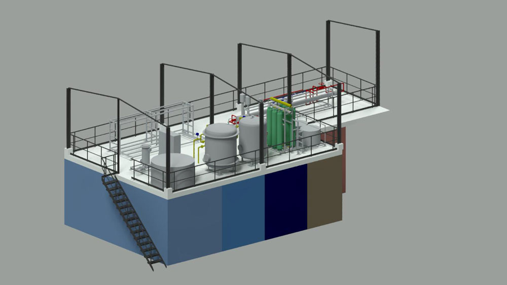
- Compact system layout required detailed plant layout drawings to fit PSF, ACF, UF skid, RO1 skid, RO2 skid, CIP system, and all dosing units within allocated footprint
4 │ ENGINEERING & DESIGN APPROACH
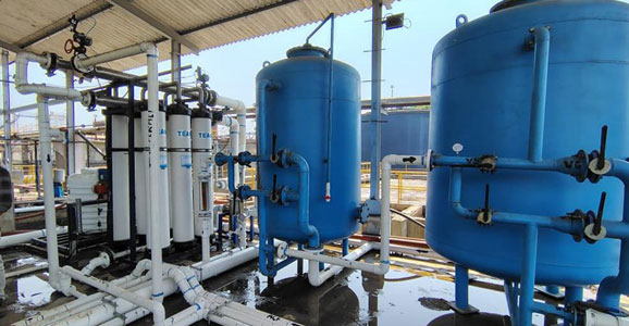
Considering the feed water parameters — particularly the high TDS, hardness, and chloride load — the BlueMaarlin team designed a multi-stage pre-treatment and polishing system: a Pressure Sand Filter (PSF) and Activated Carbon Filter (ACF) ahead of Ultrafiltration (UF), followed by a two-stage Reverse Osmosis system. This arrangement provided multiple barriers against fouling, scaling, and organic carryover to protect the RO membranes.
The UF system, using HITEC PES polymer membranes at 45 LMH flux, achieves 90% recovery at 25.68 m³/hr feed. RO Stage 1 (Hydranautics LFC-LD 8040) runs at 70% recovery, with the RO1 reject stream (6.94 m³/hr) feeding RO Stage 2. RO2 uses sea-water grade Hydranautics membranes and a high-pressure CNP pump (18.5 bar) to achieve 45% recovery, producing a final permeate of 3.12 m³/hr while concentrating the reject for ZLD or further treatment.
Water Balance (Design)
| System | Feed (m3/hr) | Permeate (m3/hr) | Reject (m3/hr) | Recovery |
|---|---|---|---|---|
| Ultrafiltration (UF) | 25.68 | 23.11 | 2.57 | 90% |
| RO Stage 1 (RO1) | 23.11 | 16.17 | 6.94 | 70% |
| RO Stage 2 (RO2) | 6.94 | 3.12 | 3.82 | 45% |
| Overall System | 25.68 | 19.29 | 3.82 | 75% |
Process Water Quality Through System
| Parameter | UF Inlet | UF Outlet | RO1 Permeate | RO2 Permeate | Unit |
|---|---|---|---|---|---|
| Flow | 25.68 | 23.11 | 16.17 | 3.11 | m3/hr |
| pH | 6–7 | 6–7 | 5–6 | 5–6 | — |
| COD | <100 | <50 | <5 | <5 | mg/L |
| BOD | <30 | <10 | <5 | <5 | mg/L |
| TDS | 2,500 | — | <50 | <100 | mg/L |
| Hardness | 1,500 | — | <30 | <50 | mg/L |
| Chloride | 1,000 | — | <30 | <50 | mg/L |
| Sulphates | <200 | — | <10 | <50 | mg/L |
| Turbidity | <3 | — | — | — | NTU |
| Temperature | 35–38 | 35–38 | 35 | 35 | °C |
5 │ PRE-TREATMENT: PSF & ACF SYSTEM
| Component | Specification |
|---|---|
| Feed Pump (PSF) | Kirloskar — 2 nos. (1W+1S), 25.68 m3/hr, 25m, CI, 3.7 kW |
| Sand Filter (PSF) | Dia 1400 mm × H 1850 mm, Sand Qty 2150 kg, Manual BFVs |
| Carbon Filter (ACF) | Dia 1600 mm × H 1850 mm, Carbon (900 IV) 1650 kg, Manual BFVs |
| Purpose | Removes TSS, turbidity, residual organics and chlorine before UF |
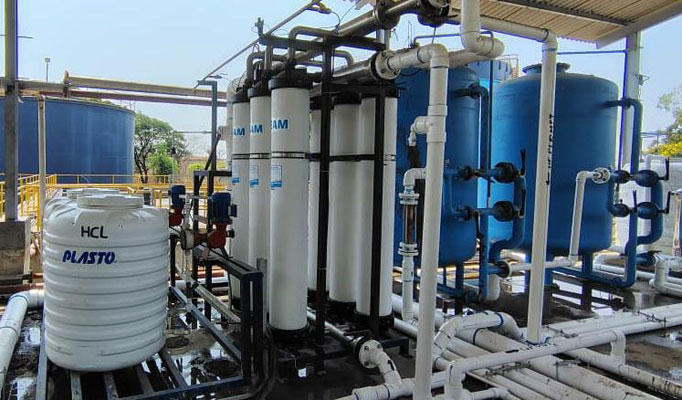
6 │ ULTRAFILTRATION (UF) SYSTEM
| Component | Specification |
|---|---|
| Membrane Make | HITEC |
| Membrane Model | RDMT-81XVI-MBM-100KD |
| Membrane MOC | PES (Polyethersulfone) |
| MWCO | 100 KDa |
| No. of Modules | 6 Nos. |
| Flux Rate | 45 LMH |
| Recovery | 90% |
| Feed Flow | 25.68 m3/hr |
| Permeate Flow | 23.11 m3/hr |
| UF Feed Pump | Kirloskar — 2 nos. (1W+1S), 25.68 m3/hr, 25m, CI, 3.7 kW |
| Backwash Pump | Kirloskar — 2 nos. (1W+1S), 84 m3/hr, 25m, CI/CF8, 22 kW |
| Basket Strainer | BMEPL SS304, 150 micron, 26 m3/hr |
| Acid Dosing Tank | Plasto HDPE, 500L, Vertical Cylindrical |
| Acid Dosing Pump | Positive Metering PP, 0–125 LPH, 3.5 kg/cm2, Electronic |
| Alkali Dosing Tank | Plasto HDPE, 500L |
| Alkali Dosing Pump | Positive Metering PP, 0–91.8 LPH, 3.5 kg/cm2, Electronic |
| Auto Butterfly Valves | Aira — 4 nos., Pneumatic Actuated, CI Body – SS Disc |
| UF Skid | MS Epoxy Painted (MSEP) |
| Piping | UPVC (feed/permeate); Feed Header UPVC |
7 │ REVERSE OSMOSIS — STAGE 1 (RO1)
| Component | Specification |
|---|---|
| Membrane Make | Hydranautics |
| Membrane Model | LFC-LD 8040 (Low Fouling Composite) |
| Housing Make | UKL FRP, 300 PSI rating |
| No. of Membranes | 25 Nos. |
| Feed Flow | 23.11 m3/hr |
| Permeate Flow | 16.17 m3/hr (~16.77 m3/hr design) |
| Reject Flow | 6.94 m3/hr (feeds RO2) |
| Recovery | 70% |
| RO1 Feed Pump | Kirloskar — 2 nos. (1W+1S), 23.11 m3/hr, 30m, CF8, 3.7 kW |
| High Pressure Pump | CNP — 2 nos. (1W+1S), 25.05 m3/hr, 10.7 bar, SS316, 15 kW, Vertical Multistage |
| Cartridge Filter | BMEPL SS304, 5 micron, 30" × 30E, 23 m3/hr, PP Spun |
| Acid Dosing | Plasto HDPE 500L + Positive Metering PP, 0–10 LPH, Electronic |
| Antioxidant Dosing | Plasto HDPE 500L + Positive Metering PP, 0–6 LPH, Electronic |
| Antiscalant Dosing | Plasto HDPE 500L + Positive Metering PP, 0–6 LPH, Electronic |
| HP & Reject Piping | SS304 SCH10 |
| Interconnecting Pipe | UPVC SCH40 |
| RO1 Skid | MS Epoxy Painted (MSEP) |
8 │ REVERSE OSMOSIS — STAGE 2 (RO2)
| Component | Specification |
|---|---|
| Membrane Make | Hydranautics |
| Membrane Model | Sea Water Grade |
| Housing Make | UKL FRP, 450 PSI rating |
| No. of Membranes | 6 Nos. |
| Feed Flow | 6.94 m3/hr (RO1 Reject) |
| Permeate Flow | 3.12 m3/hr |
| Recovery | 45% |
| RO2 Feed Pump | Kirloskar — 2 nos. (1W+1S), 7 m3/hr, 30m, CF8M, 3.7 kW |
| High Pressure Pump | CNP — 2 nos. (1W+1S), 7 m3/hr, 18.5 bar, SS316, 7.5 kW, Vertical Multistage |
| Cartridge Filter | BMEPL SS304, 5 micron, 30" × 5E, 7 m3/hr, PP Spun |
| Acid Dosing | Plasto HDPE 100L + Positive Metering PP, 0–6 LPH, Electronic |
| Antiscalant Dosing | Plasto HDPE 100L + Positive Metering PP, 0–4 LPH, Electronic |
| HP & Reject Piping | SS316 SCH10 |
| RO2 Skid | MS Epoxy Painted (MSEP) |
9 │ CIP SYSTEM & INSTRUMENTATION
| Component | Specification |
|---|---|
| CIP Tank | Plasto HDPE, 2000L |
| CIP Pump | CNP — 1 no., 25 m3/hr, 40m, SS316, 7.5 kW, Horizontal |
| CIP Cartridge Filter | BMEPL SS316, 5 micron, 30" × 12E, 26 m3/hr, PP Spun |
| Instrument | Make | Location | Qty |
|---|---|---|---|
| pH Meter | Aster | RO1 | 1 |
| Conductivity Meter | Aster | RO1 and RO2 | 4 |
| ORP Meter | Aster | RO1 | 1 |
| SDI Kit | Aster | UF | 1 |
| Pressure Gauges | Waree | UF, RO1, RO2 | 24 |
| Low Pressure Switch | Danfoss | RO1, RO2 | 4 |
| High Pressure Switch | Danfoss | RO1, RO2 | 4 |
| DP Switch | Danfoss | UF | 1 |
| Mag Flow Meter | Aster | UF Backwash | 1 |
| Rotameters | Aster | UF Permeate, RO1/RO2 P & R | 5 |
| Level Switches | — | All Dosing Tanks | 8 |
| Control Panel (UF) | Aster | Matic Type MCC | 1 |
| Control Panel (RO1/RO2) | Aster | Matic Type MCC | 1 |
| PLC Automation | — | Custom PLC sequence | 1 |
10 │ PIPING, VALVES & SCOPE OF SUPPLY
| Line | MOC |
|---|---|
| UF Piping (inlet basket strainer & after each header) | UPVC |
| UF Feed Header | UPVC |
| RO1 HP & Reject Piping | SS304 SCH10 |
| RO2 HP & Reject Piping | SS316 SCH10 |
| RO Interconnecting Piping | UPVC SCH40 |
| Flanges | BS 10 Table E Standard |
Valves
- Butterfly Valves — CI/SS, CI for on/off service
- Ball Valves — CI, SS for sampling and drain points
- Check Valves — CI, CF8 on pump discharge lines
- SS304 Nut & Bolts used at all SS304/SS316 flanges; GI Nut & Bolts for pumps and other fittings
BlueMaarlin Scope of Supply
- Process design & basic engineering; detailed engineering of all treatment units
- Supply of all equipment, instruments, piping, valves, and dosing systems within battery limits
- Supply and installation of interconnecting piping and valves
- O&M Manual post commissioning
Exclusions (Client / Mega Engineering Scope)
- MCC Panel (UF Matic + RO Matic) — supplied by Mega Engineering
- Civil works: RCC tanks, trenches, bridges, acid/alkali lining, handrailing
- 3-phase electric supply to BlueMaarlin's control panel; site wiring beyond battery limit
- Chemicals (antiscalant, acid, etc.) for commissioning and operation (first charge oil/lubricants supplied)
- Unloading, site storage, security, illumination/ventilation of plant area
- Erection and commissioning (not included in commercial offer)
11 │ DOCUMENT & DELIVERY SCHEDULE
Engineering Documents
| Document | Duration from PO |
|---|---|
| P&ID Drawing | 16 days |
| Data Sheets & Technical Documents | 25 days |
| Electrical Panel Drawings | 35 days |
| Plant Layout & Skid Drawing | 20 days |
| Quality Assurance Plan | 25 days |
| Internal Quality & Painting Reports | During dispatch |
| Test Certificates of Components | During inspection/dispatch |
| O&M Manual | After commissioning |
Supply & Commissioning Timeline
| Milestone | Duration |
|---|---|
| Inspection call (without RO membranes) | 12 weeks from date of PO |
| Dispatch to site (without RO membranes) | 14 weeks from date of PO |
| Installation & pre-commissioning check | 12–15 days after site work starts |
| Commissioning | 2–3 days after installation |
12 │ RESULTS & ACHIEVEMENTS
UF Recovery
RO1 Recovery
RO2 Recovery
UF Recovery
Total RO Membranes
PLC Automation
- 800 KLD UF-RO system successfully designed and commissioned at Chh. Shahu Sakhar Karkhana, Kagal for flushing wastewater treatment
- Multi-barrier treatment — PSF + ACF pre-treatment ahead of HITEC UF membranes, followed by two-stage Hydranautics RO — ensured robust performance against high-chloride, high-hardness sugar distillery effluent
- Custom PLC automation delivered client's requirement for high-level automated operation with minimal operator involvement
- UF system with 6 HITEC RDMT-81XVI-MBM-100KD modules achieving 90% recovery at conservative 45 LMH flux
- RO1 with 25 Hydranautics LFC-LD 8040 membranes achieving 70% recovery; RO2 with sea-water grade Hydranautics membranes at 45% recovery using CNP SS316 pump at 18.5 bar
- Treated permeate meets reuse quality: TDS <50 mg/L at RO1, <100 mg/L at RO2; Hardness <30 and <50 mg/L respectively
- Kirloskar horizontal pumps used for low-pressure duties (feed, backwash, transfer); CNP vertical multistage SS316 pumps for high-pressure RO1 (10.7 bar) and RO2 (18.5 bar) service
- Complete documentation package: P&ID, data sheets, electrical drawings, plant layout, and O&M manual delivered as per agreed schedule