IOCL ZLD System Case Study
Indian Oil Corporation Ltd. (IOCL), Haryana, India
Polymer Manufacturing Plant
1 │ PROJECT OVERVIEW
| End Customer | Indian Oil Corporation Ltd. (IOCL) |
|---|---|
| Plant Type | Polymer Manufacturing Plant (Polypropylene / Polyethylene) |
| Site Location | Haryana, India |
| OEM / Coordinator | Suyash Equipments Pvt. Ltd. |
| Executed By | BlueMaarlin Environmental Pvt. Ltd. (BMEPL), Pune |
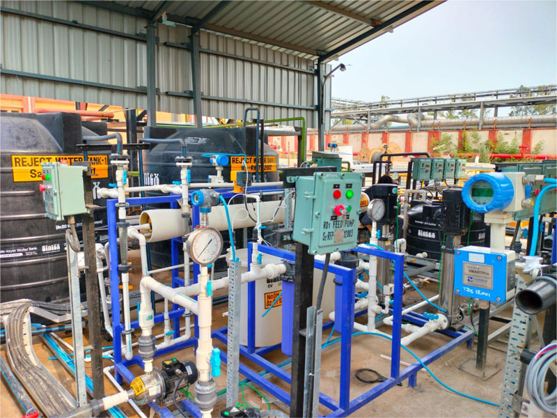
| System Type | Zero Liquid Discharge (ZLD) — UF + RO Stage 1 + RO Stage 2 |
| Feed Source | Process wastewater from polymer manufacturing operations |
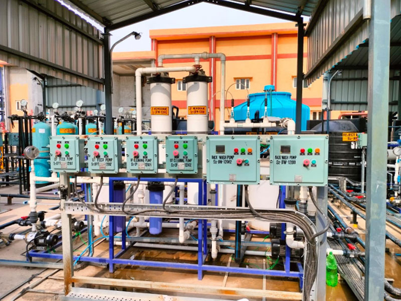
| UF Feed Flow | 5 m³/hr — 1 stream, 2 membranes (HITEC-TEAM RDMT-EM-81XVI-MBM100KD) |
| RO1 Capacity | ~10 m³/hr — 4 membranes (Hydranautics LFC3LD / DuPont ESPA 8040) |
| RO2 Capacity | ~4 m³/hr — 4 membranes (Hydranautics LFC3LD / DuPont ESPA 4040) |
| Control System | HMI + PLC Panel with RS485 instrumentation (separate for UF, RO1, RO2) |
| ZLD Compliance | Full Zero Liquid Discharge — no effluent discharge to environment |
| Membrane Make | HITEC-TEAM (UF) | Hydranautics / DuPont (RO1 & RO2) |
| Pump Make | CNP Pumps SS316 (UF) | CNP Pumps SS304 (RO1 & RO2) |
| Dosing Chemical | Pelican 399 Antiscalant + Bio Fouling chemical (RO2) |
2 │ ABOUT THE END CUSTOMER — IOCL POLYMER PLANT
Indian Oil Corporation Ltd. (IOCL) is India's largest public sector oil and gas company and one of the Fortune 500 companies.
IOCL's polymer manufacturing plants produce a range of polyolefins — primarily Polypropylene (PP) and High/Linear Low Density Polyethylene (HDPE/LLDPE) — using Ziegler-Natta and metallocene catalyst systems.
These products serve the packaging, automotive, textile, and piping sectors across India.
The Haryana facility operates as an integrated petrochemical complex, receiving feedstock (propylene and ethylene) from IOCL's refinery operations and processing it through continuous slurry or gas-phase polymerisation reactors to produce polymer pellets for sale to downstream industries.
A polymer manufacturing plant generates several distinct wastewater streams that require careful treatment before any possibility of reuse or discharge. The principal sources and characteristics are: Wastewater Source Contaminants Characteristics
| Wastewater Source | Contaminants | Characteristics |
|---|---|---|
| Reactor wash water & purge streams | Polymer fines (oligomers), catalyst residues (Ti, Al, Mg), hydrocarbons, hexane / heptane diluents | High TSS, emulsified organics, traces of heavy metal catalysts, variable TDS |
| Cooling tower blowdown | Dissolved minerals (Ca, Mg, Na, HCO₃, SO₄, Cl), scale inhibitors, biocides, corrosion inhibitors | High TDS, high hardness, elevated conductivity |
| Equipment & vessel washdowns | Polymer fines, residual catalyst, process chemicals (antioxidants, stabilisers, surfactants) | Variable TSS and COD, trace organics |
| Steam condensate & utility drainage | Low dissolved solids, trace hydrocarbons from steam tracing leaks | Relatively clean but cannot be discharged due to ZLD mandate |
| Pelletising & degassing system drainage | Residual monomer (propylene/ethylene), additives, antistatic agents | Low volume but potential VOC content |
| Laboratory & quality control waste | Solvents (xylene, decalin for viscosity testing), catalyst residues, cleaning chemicals | Low volume, variable chemistry |
As a PSU operating under strict CPCB and Haryana State Pollution Control Board (HSPCB) regulations, IOCL's polymer plant is required to maintain Zero Liquid Discharge status — meaning all wastewater generated on-site must be treated and fully recovered or disposed as dry solid waste, with zero liquid effluent reaching any water body or drain.
3 │ ENGINEERING CHALLENGES
Process & Wastewater Challenges
- Polymer fines (oligomers and fine PP/PE particles) in the feed stream are hydrophobic and tend to coat UF membranes differently from biological or inorganic colloids — requiring careful flux design and regular acid/caustic CIP
- Catalyst residues (Ziegler-Natta: TiCl₄, AlEt₃, MgCl₂ support) contribute trace metals including titanium, aluminium, and magnesium to the wastewater, which can foul RO membranes if not removed by UF pre-treatment
- Cooling tower blowdown typically carries 3,000–6,000 ppm TDS with high calcium hardness, sulphates, and chlorides — posing CaSO₄ and CaCO₃ scaling risk on RO membranes
- Residual scale inhibitors and biocides from the cooling system are often incompatible with polyamide RO membranes and can cause membrane degradation — requiring careful antiscalant (Pelican 399) selection and bio-fouling inhibitor dosing
- IOCL being a PSU with stringent procurement and QA requirements: all equipment required compliance with applicable IS/ASTM standards, and vendor qualifications (CNP, Hydranautics/DuPont, Baumer, Danfoss, Aira/UFLOW, Aster) were pre-approved by Suyash Equipments / IOCL
System Design Challenges
- Two-stage RO design (RO1 at 8040 elements, RO2 at 4040 elements) required because the reject volume and TDS from RO1 alone are too large to send directly to evaporation — RO2 recovers additional water and reduces the final concentrate volume going to ZLD disposal
- HMI + PLC-based integrated control for all three subsystems (UF, RO1, RO2) — required RS485 communication from all instruments (Aster pH meter with RS485, Aster CT650 conductivity meters with RS485) for data logging and remote monitoring at IOCL's DCS/SCADA
- IOCL's Zero Liquid Discharge mandate meant RO2 reject could not simply be discharged — a downstream evaporator/ATFD (Agitated Thin Film Dryer) stage was planned beyond BMEPL's scope, requiring RO2 reject to meet specific TDS and flow rate specifications
- Dual 1W+1S pump configurations throughout (UF feed, backwash, CIP, RO1 feed, RO1 HP, RO2 feed, RO2 HP) for 24/7 plant operation reliability — critical for a PSU facility that cannot tolerate unplanned downtime
4 │ ENGINEERING & DESIGN APPROACH
BlueMaarlin's design team adopted a three-stage water recovery train specifically engineered for the polymer manufacturing effluent matrix. The system was designed to operate in series: UF pre-treatment removes polymer fines, catalyst residues, and colloidal matter; RO Stage 1 recovers the bulk of the treated water (targeting ~70 75% recovery); and RO Stage 2 processes the RO1 reject to extract additional recoverable water, reducing the final brine volume sent to the client's downstream ZLD disposal (evaporator/ATFD).
The UF system uses HITEC-TEAM Modified Polyethersulfone (MPES) Multibore membranes (In-to-Out configuration) — a superior choice for hydrocarbon-contaminated streams because multibore membrane geometry is significantly more fouling-resistant than single-bore hollow fibre in the presence of polymer fines and oily droplets. The In-to-Out flow path allows better cleaning of the external surface during backwash, critical for effective CIP with caustic and HCl.
For RO1 and RO2, Hydranautics LFC3LD (Low Fouling Composite 3 Low Differential) or DuPont ESPA membranes were specified. The LFC series is specifically engineered for water with elevated organic fouling potential — its thin film composite polyamide construction with a proprietary surface coating reduces the adhesion of organic foulants compared to standard high-rejection RO elements. This is particularly important given the potential for oligomers, surfactants, and scale inhibitor carryover from the polymer plant cooling system.
Flow Balance (Design)
| Stage | Feed | Product / Permeate | Reject | Destination |
|---|---|---|---|---|
| UF | 5 m3/hr | ~4.5 m3/hr (90% recovery) | ~0.5 m3/hr backwash | Permeate → RO1 |
| RO1 | ~10 m3/hr (including recycle) | ~7–7.5 m3/hr permeate (70–75%) | ~2.5–3 m3/hr reject | Permeate → Product reuse; Reject → RO2 |
| RO2 | ~4 m3/hr | ~2.5–2.8 m3/hr permeate | ~1.2–1.5 m3/hr brine | Permeate → Product reuse; Brine → Evaporator/ATFD |
| Final Product Water | — | ~10 m3/hr total | — | Process water reuse at IOCL plant |
| Final Discharge | — | — | ZERO | Full ZLD — brine to evaporator |
5 │ ULTRAFILTRATION (UF) SYSTEM
| Streams | 1 No. |
|---|---|
| Feed Capacity | 5 m3/hr per stream |
| Membranes | 2 Nos. per skid (HITEC-TEAM RDMT-EM-81XVI-MBM100KD) |
| Membrane MOC | Modified Polyethersulfone (MPES) — Multibore |
| Configuration | In-to-Out (Inside-Out flow path) |
| End Cap MOC | PPGF (Polypropylene Glass Filled) |
| Component | Make / Model | Specification |
|---|---|---|
| UF Feed Pump (1W+1S) | CNP Pumps — Model CHL 4-40 | Qty: 2, SS316 all wetted parts, 3-Phase, Multistage Horizontal Centrifugal |
| Micron Filtration | BlueMaarlin UPVC | Qty: 3 (2 for inlet feed + 1 for CIP), Capacity 5,000 LPH each |
| UF Membrane | Membrane HITEC-TEAM — RDMT-EM-81XVI-MBM100KD | Qty: 2, Area 81 m2 each, Modified PES Multibore, In-to-Out, 100 KDa, PPGF End Caps |
| Backwash Pump | CNP Pumps — Model CHL 20-20 | 3HP, 3-Phase, Multistage Horizontal |
| Caustic Dosing Pump | Initiative Engineering Edose Mega — PP | Qty: 1, 40 LPH @ 3 kg/cm2, Dosing Tank: 225L LLDPE (BMEPL) |
| HCl Dosing Pump | Initiative Engineering Edose Mega — PP | Qty: 1, 50 LPH @ 2 kg/cm2, Dosing Tank: 225L LLDPE (BMEPL) |
| Hypo Dosing Pump | Initiative Engineering Edose Mega — PP | Qty: 1, 40 LPH @ 2 kg/cm2, Dosing Tank: 225L LLDPE (BMEPL) |
| CIP Pump | CNP Pumps — Model CHL 4-30, SS316 | CIP Tank: 500L Plasto (BMEPL) |
| Pressure Gauges | Baumer SS | Qty: 5, Range 0–7 kg/cm2, 65NB dial, Online, Glycerin filled |
| Auto Solenoid Valves | AIRA / Uflow SS | Qty: 5, Electrically actuated NC — 40NB (×3) and 50NB (×2) |
| Rotameters | Aster Manual | Qty: 2 — 10,000 LPH and 7,500 LPH, Online |
| UF Skid | BMEPL | MS Powder Coated, 1W+1S configuration |
| Piping | Astral UPVC SCH40 | 1 set for 1W+1S |
Why HITEC-TEAM Multibore Membranes for Polymer Plant Effluent
- Multibore geometry (7 bores per fibre) provides significantly higher mechanical stability than single-bore hollow fibre — critical for withstanding the backwash pressures needed to dislodge polymer fines from membrane surfaces
- Modified Polyethersulfone (MPES) shows better resistance to the hydrophobic organic compounds (oligomers, catalyst residue films) present in polymer manufacturing wastewater compared to standard PES
- In-to-Out configuration allows polymer fines to be deposited on the external surface of the multibore fibre — more amenable to aggressive CIP cleaning (caustic + HCl + hypochlorite) than inside-out deposition
- Three separate dosing systems (caustic, HCl, hypochlorite) enable a comprehensive CIP protocol: caustic soak removes organic/polymer fines, HCl removes mineral scales from catalyst residues, hypochlorite provides biofouling control
6 │ REVERSE OSMOSIS — STAGE 1 (RO1)
| Component | Make / Model | Specification |
|---|---|---|
| RO1 Feed Pump (1W+1S) | CNP Pumps — Model CHL 8/40 | Qty: 2 (1W+1S), SS304, 3-Phase, Multistage Horizontal Centrifugal |
| Micron Cartridge Filter | BlueMaarlin — SS304 | Qty: 2 (1 for RO inlet + 1 for CIP), Capacity 10 m³/hr each |
| RO Membranes | Hydranautics / DuPont — LFC3LD or ESPA 8040 | Qty: 4, Polyamide Thin Film Composite — Low Fouling Composite series |
| RO Pressure Housings | UKL FRP | Qty: 2, Size: 8040 2E, End Port, 450 PSI pressure rating |
| High Pressure Pump | CNP Pumps — Model CDL 8/16 | SS304, 7.5 HP, 3-Phase, Vertical Multistage Centrifugal |
| Antiscalant & CIP System | — | CIP Tank: 1000L; Antiscalant dosing included |
| Pressure Gauges (Online) | Baumer SS | Qty: 2, Range 0–7 kg/cm², 65NB dial, Glycerin filled |
| Pressure Gauges (HP/Panel) | Baumer SS | Qty: 2, Range 0–21 kg/cm², 65NB dial, Glycerin filled |
| Solenoid Valves | Aira / UFLOW SS | Qty: 2, 40NB, Normally Closed |
| Rotameters | Aster-Embark Polycarbonate | Qty: 2 — 10,000 LPH and 5,000 LPH, 40NB, Online |
| Low Pressure Switch | Danfoss | Qty: 1 |
| High Pressure Switch | Danfoss | Qty: 1 |
| pH Meter | Aster PO650 (Regular — clear water) | RS485 output — Qty: 1 |
| Conductivity Meter | Aster CT650 | 0–2,000 ppm, RS485 output — Qty: 1 |
| Float Switches | Blue Seas | Qty: 2, 10m cable |
| Control Panel | HMI + PLC Panel (1W+1S) | Qty: 1 — integrated HMI with PLC for automated RO1 operation |
| RO1 Skid | BMEPL MS Powder Coated | With hardware, wiring, and cabling — 1W+1S set |
| Piping (Low Pressure) | Astral UPVC | Up to high pressure pump |
| Piping (HP Line) | SS304 | High pressure line from HP pump to membrane housings |
Why Hydranautics LFC3LD / DuPont ESPA for Polymer Plant Water
- LFC3LD (Low Fouling Composite 3 Low Differential) is Hydranautics' premium antifouling membrane — its modified surface coating significantly reduces adhesion of organic molecules, surfactants, and scale inhibitor carryover from polymer plant cooling systems.
- The ‘Low Differential’ designation means reduced pressure drop across the element length — important when operating at elevated temperatures or when feed contains dissolved organics that could cause compaction.
- DuPont ESPA (Energy Saving Performance Architecture) membranes offer high rejection at lower operating pressures — reducing HP pump duty and energy consumption for the polymer plant ZLD system.
- 8040 size elements in 2-element housings (2E, 450 PSI rated) provide the right balance of flow capacity and residence time for the expected feed TDS range from polymer plant wastewater.
7 │ REVERSE OSMOSIS — STAGE 2 (RO2)
| Component | Make / Model | Specification |
|---|---|---|
| RO2 Feed Pump (1W+1S) | CNP Pumps — Model CHL 2/30, SS316 | Qty: 2 (1W+1S), Capacity 4 m³/hr @ 3.0 kg/cm², 0.5HP, 3-Phase — SS316 for higher TDS/corrosive reject feed |
| Micron Cartridge Filter | BlueMaarlin UPVC | Qty: 2 (1 for RO inlet + 1 for CIP), Capacity 5 m³/hr each |
| RO Membranes | Hydranautics / DuPont — LFC3LD or ESPA 4040 | Qty: 4, Polyamide Thin Film Composite, 4040 size — sized for the lower flow/higher TDS reject stream |
| RO Pressure Housings | UKL FRP | Qty: 2, Size: 8040 2E end port, 450 PSI — accommodates 4040 elements |
| High Pressure Pump (1W+1S) | CNP Pumps — Model CDL 8/16, SS304 | Qty: 2 (1W+1S), 4 m³/hr, 7.5HP, 3-Phase, Vertical Multistage |
| Antiscalant Dosing Pump | Initiative Engineering Edose | Qty: 2, Capacity 12 LPH @ 3.5 kg/cm², PP |
| Dosing Tanks (Antiscalant + BioFouling) | LLDPE | Qty: 2, 100L each; Chemical: Pelican 399 + Bio Fouling inhibitor, 5L each (first charge) |
| Pressure Gauges (0–7 kg/cm²) | Baumer SS | Qty: 2, 65NB, Online, Glycerin filled |
| Pressure Gauges (0–21 kg/cm²) | Baumer SS | Qty: 2, 65NB, Online, Glycerin filled |
| Solenoid Valve | Aira / UFLOW SS | Qty: 1, 40NB, Normally Closed |
| Rotameters | Aster-Embark Polycarbonate | Qty: 2 — 2,400 LPH and 5,000 LPH, 40NB, Online |
| Low Pressure Switch | Danfoss | Qty: 1 |
| High Pressure Switch | Danfoss | Qty: 1 |
| Conductivity Meter | Aster CT650 | 100–20,000 ppm range (higher range for concentrated RO2 reject), RS485 output — Qty: 1 |
| Float Switches | Blue Seas | Qty: 2, 10m cable |
| Control Panel | HMI + PLC Panel (1W+1S) | Qty: 1 — integrated HMI + PLC for RO2 automation |
| RO2 Skid | BMEPL MS Powder Coated | With hardware, wiring, cabling — 1W+1S set |
| Piping (Low Pressure) | Astral UPVC | Up to high pressure pump |
| Piping (HP Line) | SS304 | High pressure RO2 membrane circuit |
Design Notes — RO2 vs RO1 Differences
- RO2 feed pump specified in SS316 (vs SS304 for RO1) — the higher TDS and potentially more aggressive chemistry of the RO1 reject concentrate justifies the step up to SS316 for improved corrosion resistance
- 4040 membranes selected for RO2 (vs 8040 for RO1) — the lower volumetric flow rate of the reject stream does not justify full 8040 elements; 4040 elements provide adequate flow velocity and residence time for the 4 m³/hr RO2 feed
- Conductivity meter for RO2 specified at 100–20,000 ppm range (vs 0–2,000 ppm for RO1) — reflecting the much higher TDS of the concentrated brine being processed in RO2
- Pelican 399 antiscalant specifically dosed in RO2 to combat the elevated scaling potential of the concentrated polymer plant brine (higher Ca, SO₄, silica concentration factors)
8 │ INTEGRATED HMI + PLC CONTROL SYSTEM
All three subsystems (UF, RO1, RO2) are controlled via individual HMI + PLC panels, with RS485 instrument communication enabling data logging and integration with IOCL's plant DCS/SCADA infrastructure. This is critical for a PSU facility where all process data must be recorded, trended, and accessible for compliance reporting to HSPCB.
| System | Instruments with RS485 | PLC Automation Features |
|---|---|---|
| UF System | None specified for RS485 — manual rotameters and pressure gauges with PLC I/O | Auto backwash sequence, CIP initiation, solenoid valve sequencing (5 × SV), dosing interlocks (caustic/HCl/hypo), float switch alarms |
| RO1 System | Aster DO650 pH meter (RS485), Aster CT650 conductivity 0–2000 ppm (RS485), Danfoss LP/HP switches | Auto-start/stop, low pressure shutdown (LPS), high pressure trip (HPS), flush sequence, conductivity trend monitoring, pH monitoring for membrane protection, float switch alarms |
| RO2 System | Aster CT650 conductivity 100–20,000 ppm (RS485), Danfoss LP/HP switches | Auto-start/stop, high pressure trip, conductivity monitoring of permeate and reject for ZLD compliance verification, float switch alarms, antiscalant/biofouling dosing interlocks |
- RS485 instrumentation enables IOCL to integrate the entire water treatment system into their existing plant control network for centralised monitoring and regulatory data reporting
- Separate HMI screens for UF, RO1, and RO2 allow operators to view real-time flow, pressure, conductivity, and pH data without needing to access multiple physical panels
- PLC interlocks ensure that RO1 cannot start if UF permeate tank is empty, and RO2 cannot start if RO1 reject tank is below minimum level — preventing dry-run damage to SS304/SS316 pumps
9 │ OPERATIONAL DATA — LIVE SHIFT READING
The UF + RO1 + RO2 system supplied by BlueMaarlin forms the water recovery core of IOCL's ZLD system at the Haryana polymer plant. The treated permeate from both RO stages is recycled to plant as process water or cooling tower makeup — reducing freshwater consumption. The concentrated brine from RO2 is directed to IOCL's downstream evaporation or ATFD (Agitated Thin Film Dryer) system for final drying to solid waste, completing the zero liquid discharge loop.
| Stage | Technology | Supplier | Output |
|---|---|---|---|
| Primary Treatment | ETP (equalisation, neutralisation, clarification) | Client scope / existing | Clarified effluent |
| Pre-treatment | Ultrafiltration (UF) | BlueMaarlin / BMEPL | Particle-free permeate (5 m³/hr) |
| First RO Stage | Reverse Osmosis RO1 | BlueMaarlin / BMEPL | High-quality permeate for reuse |
| Second RO Stage | Reverse Osmosis RO2 | BlueMaarlin / BMEPL | Additional water recovery from RO1 reject |
| Thermal ZLD Stage | Evaporator / ATFD (planned) | Client / separate scope | Zero liquid — dry salt cake |
- CPCB/MoEFCC ZLD notification for petrochemical complexes mandates that all process effluent must be treated and reused, with no discharge to any water body, drain, or land
- HSPCB (Haryana State Pollution Control Board) requires real-time online monitoring of key parameters including TDS, conductivity, pH, and flow rates — enabled by the RS485 instrumentation throughout the BMEPL system
- The two-stage RO architecture (RO1 → RO2) minimises the volume of brine reaching the thermal evaporation stage, directly reducing IOCL's evaporator operating cost and steam consumption — the most energy-intensive step in the ZLD chain
- Product water (RO1 + RO2 combined permeate) is returned to the plant as cooling tower makeup, reducing fresh demineralised water consumption and lowering operational costs
10 │ RESULTS & ACHIEVEMENTS
- Full ZLD-compliant UF + RO1 + RO2 water treatment system successfully designed and supplied for Indian Oil Corporation Ltd.'s polymer manufacturing plant in Haryana through OEM partner Suyash Equipments Pvt. Ltd.
- HITEC-TEAM Multibore Modified PES UF membranes (2 × 81 m², In-to-Out, RDMT-EM-81XVI-MBM100KD) selected specifically for polymer plant effluent — their multibore geometry and MPES chemistry provide superior fouling resistance against polymer fines and catalyst residue carryover compared to standard hollow fibre membranes
- Hydranautics LFC3LD / DuPont ESPA 8040 membranes in RO1 and 4040 in RO2 provide low-fouling performance critical for the complex organic and inorganic chemistry of polymer manufacturing wastewater (cooling tower blowdown + process drains)
- Dual 1W+1S pump configurations throughout all three subsystems ensure 24/7 operational reliability for the IOCL facility — no single point of failure in any pump circuit
- HMI + PLC control with RS485 instrumentation (Aster pH and conductivity meters) enables integration with IOCL's plant DCS/SCADA for centralised monitoring, data logging, and HSPCB compliance reporting
- Two-stage RO design minimises the brine volume sent to downstream thermal evaporation — directly reducing IOCL's evaporator steam consumption and operating cost in their ZLD system
- Project executed through Suyash Equipments Pvt. Ltd. as OEM partner — demonstrating BlueMaarlin's capability to serve PSU and large industrial clients through established equipment supplier channels
- CNP Pumps SS316 (UF), SS304 (RO1/RO2 HP), and Pelican 399 antiscalant selection validated for polymer plant wastewater chemistry in consultation with client's process team