Maharashtra Fasteners ZLD Case Study
Maharashtra Fasteners (NextGen, Markal, Maharashtra), Maharashtra,
India
Sugarcane-Based Distillery
1 │ PROJECT OVERVIEW
| End Customer | Maharashtra Fasteners (NextGen), Markal, Maharashtra |
| Industry | Electroplating & Fasteners Manufacturing |
| OEM / Coordinator | Oxygreen Enviro, Pune |
| Executed By | BlueMaarlin Engineering Pvt. Ltd. (BMEPL), Pune |
| System Type | Full Zero Liquid Discharge (ZLD) — UF + RO1 + RO2 + Single Effect Evaporator |
| Feed Source | Plating Effluent Treatment Plant (ETP) outlet |
| Feed Flow Rate | 40 KLD (12-hour operation) from ETP |
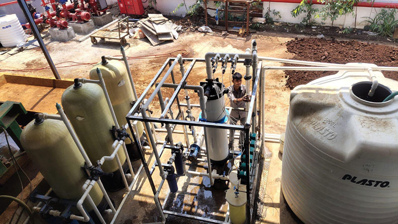
| UF Feed | 5 m3/hr |
| RO1 Capacity | 5–6 m3/hr (Hydranautics Low Fouling, 2 × 8040 3E housings, 6 membranes) |
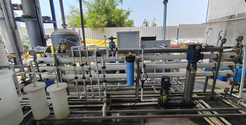
| RO2 Capacity | ~2 m3/hr (Hydranautics Sea Water, 3 × 4040 4E housings, 12 membranes) |
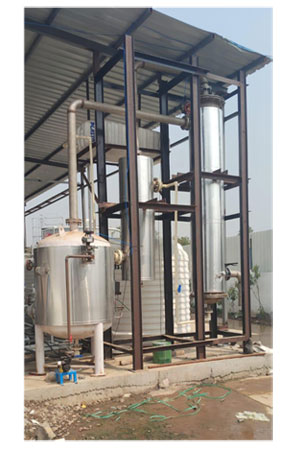
| SEE Capacity | 300 LPH (7.2 m3/day) — designed, manufactured, and supplied in-house by BMEPL |
| SEE Feed | RO2 reject / concentrated brine (4% TDS feed → 35% concentrated product) |
| ZLD Compliance | Yes — zero liquid discharge to environment |
| Quotation Ref. | BME-04012401, dated 31-07-2024 |
| SEE Proposal Ref. | BMEPL/MEE/QT/23901/Rev-00, dated 28-09-2022 |
| Project Value (UF+RO) | INR 18,60,000 + GST @ 18% = INR 21,96,423 |
| SEE Value | INR 10,00,000 (ex-works) |
2 │ CLIENT REQUIREMENT & PROJECT BACKGROUND
Maharashtra Fasteners (operating under NextGen at Markal, Maharashtra) is an electroplating and fasteners manufacturing facility. The plating process generates two distinct wastewater streams — highly acidic streams from nitric baths, HCl rinses, passivation, and anodic processes (pH ~1, TDS ~13,000 ppm), and alkaline streams from degreasing, descaling, plating bath rinses, and anodic operations (pH up to 14, TDS ~13,000 ppm).
After primary ETP treatment (equalisation, neutralisation, clarification, PSF, ACF), the combined treated effluent still contained approximately 6,000 ppm TDS, making it unsuitable for direct discharge or reuse. A full Zero Liquid Discharge (ZLD) system was required to ensure no liquid effluent leaves the facility — a regulatory necessity for electroplating operations under MPCB / CPCB guidelines.
Client's Key Requirements
- Full ZLD compliance: all treated water to be recovered and all concentrated reject to be evaporated to zero liquid discharge
- UF + two-stage RO for maximum water recovery before evaporation — minimising evaporator load and operating cost
- Single Effect Evaporator (SEE) as the final ZLD stage to evaporate RO2 reject brine and produce dry concentrate
- PLC or Matic-based integrated control panel for UF, RO1, and RO2 systems
- Compact, robust system capable of handling aggressive plating effluent chemistry including dissolved heavy metals (Ni, Zn, Cr), chelants, and plating organics
| Stream | Pre-Neutralisation pH | Pre-Neutralisation TDS | Post-ETP Mixed TDS |
|---|---|---|---|
| Acidic (Nitric/HCl/Passivation, 10 KLD) | ~1 | ~13,000 ppm | ~8,000 ppm (after NaOH) |
| Alkaline (Degreasing/Plating, 15 KLD) | ~14 | ~13,000 ppm | ~11,000–15,000 ppm |
| Combined (post ETP, 25 KLD) | ~8 | — | ~6,000 ppm (after settling) |
3 │ ENGINEERING CHALLENGES
Technical Challenges — UF + RO Design
- High feed TDS (~6,000 ppm post-ETP) with complex ionic chemistry (dissolved Ca2+, SO42−, Fe2+/Fe3+, Ni, Zn, Cr, residual chelants) required careful RO membrane selection — Hydranautics Low Fouling Composite (LFC) for RO1 and Sea Water grade for RO2
- RO2 operating at extreme pressure (~210m head, ~21 bar via CNP CDH 2-22 + CDH 2-4 combination pump) to achieve recovery from a very high TDS reject stream
- 4040 sea-water grade membranes (3 × 4E housings, 12 membranes) used in RO2 to handle the concentrated brine — 600 PSI pressure-rated FRP housings (UKL/DAX)
- Plating effluent contains chelating agents (EDTA), surfactants, and trace heavy metals that can bypass conventional pre-treatment — requiring UF (HITEC/QUA PES/PVDF, 100m2, In-to-Out) as the critical barrier before RO
- SEE design to handle 4% TDS feed (40,000 ppm) and concentrate to 35% (3,50,000 ppm) — requiring SS316 product-contact surfaces throughout to resist aggressive concentrated brine
ZLD System Design Challenge — SEE
- Single Effect Evaporator (300 LPH capacity, 300 kg/hr evaporation) designed, engineered, and manufactured entirely in-house at BlueMaarlin's Pune workshop — representing BMEPL's full thermal process capability
- Steam generation within the system (430 kg/hr steam requirement) — plant configured as self-steam-generating ZLD system
- Vacuum operation at ≤55°C product temperature to minimise heat degradation of concentrated plating salts and reduce energy consumption
- SS316 tubes, tube sheets, bonnets, and vapour separator with forced circulation design to prevent salt deposition on heat transfer surfaces
4 │ ULTRAFILTRATION (UF) SYSTEM
| Component | Specification |
|---|---|
| Raw Water Pump | CNP/Xylem SS304 — 1 no., 5 m3/hr @ 20.5m, Model CHL-FT-4-30, 0.75HP / 0.55 kW, Multistage Horizontal, IE2 |
| Bag Filter (×2) | BMEPL UPVC/FRP — 5 m3/hr, 1.5" Flanged, UPVC, 4.5"×20" cartridge, 1 × Spun 5 micron |
| UF Membrane | HITEC / QUA — PES or PVDF, RDMT-EM-XVI-100-MBM, 100KD, In-to-Out, 100 m2 area — 1 module |
| Solenoid Valves | Aira/Equip SS — 25NB, NC (×2); CI — 40NB, NC (×2) |
| Backwash Pump | CNP/Xylem SS304 — 18 m3/hr @ 21m, Model CHL20-20, 3HP, Horizontal Multistage, IE2, No negative suction |
| Dosing Pumps (Caustic + Hypo) | Initiative Engineering PP — 4 nos., 0–10 LPH @ 3 kg/cm2, Edose MEGA, Electrically Actuated |
| Dosing Pumps (HCl) | Initiative Engineering PP — 2 nos., 0–10 LPH @ 2 kg/cm2, Edose MEGA, Electrically Actuated |
| Dosing Tanks | PC LDPE — 3 nos., 30 Litres each with lid |
| Float Switches | BS Plastic — 2 nos., 5m cable |
| Pressure Gauges | FLO/Baumer SS304 — 0–7 kg/cm2, Glycerin filled, 65NB dial — 3 nos. |
| Rotameter (Feed+Perm) | Aster F7500L — 1" M end conn., 7500 LPH — 2 nos. |
| Rotameter (Backwash) | Aster F15000L — 1.5" M end conn., 15,000 LPH — 1 no. |
| UF Skid | BMEPL MSEP — dosing and CIP tanks on ground |
| Piping | Astral UPVC SCH40 — white piping |
5 │ REVERSE OSMOSIS — STAGE 1 (RO1)
| Component | Specification |
|---|---|
| RO1 Feed Pump | CNP/Xylem SS304 — 1 no., 5 m3/hr @ 20.5m, Model CHL-4-30, 0.75HP / 0.55 kW, Multistage Horizontal, IE2 |
| Cartridge Filter Housings | PP Jumbo — 2 nos.; PP Spun — 2 nos. |
| High Pressure Pump | CNP SS304 — 1 no., 6 m3/hr @ 140m head, Model CDL 8-16, 7.5HP, Vertical Multistage |
| RO Membrane Housings | UKL/DAX FRP — 8040 size, 3 elements/housing, 300 PSI, Side Port — 2 nos. |
| RO Membranes | Hydranautics / Veolia / Toray — Low Fouling Composite (LFC) — 6 nos. |
| Rotameters | Aster — 3 nos. (permeate, reject, feed) |
| Pressure Gauges | 4 nos. |
| Solenoid Valve | 1 no. |
| RO1 Skid | MSPC — Mild Steel Powder Coated |
| Piping | Low pressure: UPVC SCH40 | High pressure: SS304 |
6 │ REVERSE OSMOSIS — STAGE 2 (RO2)
| Component | Specification |
|---|---|
| RO2 Feed Pump | CNP SS304 — 1 no., 2 m3/hr @ 20.5m, Model CHL-2-20 SS316, 0.75HP / 0.55 kW, Multistage Horizontal, IE2 |
| Cartridge Filter | PP Jumbo housing — 1 no.; PP Spun cartridge — 1 no. |
| High Pressure Pump | CNP/Xylem SS316 — 1 no., 3.36 m3/hr @ 210m head, Model CDH 2-22 + CDH 2-4 combination, High pressure SS316 |
| RO Membrane Housings | UKL/DAX FRP — 4040 size, 4 elements/housing, 600 PSI — 3 nos. |
| RO Membranes | Hydranautics — Sea Water grade / PRO LFI — 12 nos. |
| Rotameters | Aster — 3 nos. (permeate, reject, reject recirculation) |
| Pressure Gauges | 4 nos. |
| Solenoid Valve | 1 no. |
| RO2 Skid | MSPC — Mild Steel Powder Coated |
| Piping | Low pressure: UPVC SCH40 | High pressure: SS316 |
| Note | RO2 reject (brine) feeds the Single Effect Evaporator as SEE feed |
Control Panel
1 common PLC or Matic-based control panel for UF, RO1, and RO2 systems — integrated, pre programmed control with alarm interlocks for all stages
7 │ SINGLE EFFECT EVAPORATOR (SEE) — IN-HOUSE DESIGN & MANUFACTURE
The Single Effect Evaporator (SEE) is the cornerstone of this ZLD system — it is BlueMaarlin's own in-house designed, engineered, and manufactured thermal evaporation unit. The SEE receives the concentrated brine from RO2 reject and evaporates 300 kg of water per hour, concentrating the feed from 4% TDS (40,000 ppm) to 35% TDS (3,50,000 ppm) for final disposal as dry cake or crystallised salt — completing the Zero Liquid Discharge loop.
Design Basis
| Parameter | Value |
|---|---|
| Design Scheme | Single Effect Evaporator (SEE) with Forced Circulation |
| Plant Capacity | 300 LPH (water evaporation) |
| Feed Rate | 400 kg/hr (feed to evaporator) |
| Water Evaporation Rate | 300 kg/hr |
| Feed TDS | 4.0% w/w (40,000 ppm) |
| Concentrated Product | 35% w/w (3,50,000 ppm) |
| Feed pH | 6 – 8 |
| Feed Temperature | 30°C (inlet) |
| Product Temperature | ≤ 55°C (vacuum operation) |
| Steam Required | 430 kg/hr (generated within system) |
| Cooling Water Inlet | 30°C |
| Cooling Water Outlet | 36°C |
| Power Consumed | 200 kW |
| Power Connected | 250 kW |
| Area Classification | Non-Hazardous / Non-Explosive |
Key Equipment — Single Effect Evaporator
| Component | MOC (Product Contact) | MOC (Non-Contact) | Notes |
|---|---|---|---|
|
Evaporator Column
(Vertical Fixed Tube Sheet) |
Tubes: SS316 | Tube Sheets: SS316 | Bonnets: SS316 | Shell: SS304 | Body Flanges: MS + SS316 cladding | Supports: MS anticorrosive | Forced circulation; detachable top cover for tube cleaning |
|
Pre-Heater
(Vertical Fixed Tube Sheet) |
Tubes: SS316Ti | Tube Sheets: SS316L | Bonnets: SS316L | Shell: SS304L | Flanges: MS + SS316 cladding | Feed preheating before evaporator column |
|
Surface Condenser
(Vertical Fixed Tube Sheet) |
Shell: SS304L | Tubes: SS304L | Tube Sheets: SS304L | Dish End: MS anticorrosive | Flanges: MS + SS304 cladding | Vapour condensed on shell side; CW in tubes |
| Vapour Separator | SS316 (product contact) | Flanges: MS anticorrosive | Vertical cylindrical; centrifugal separation; vortex breaker; sight/light glass |
| Condensate Pot | SS304L | — | Collects all process condensate; sight glass |
| Level Pot (×3) | SS316L | — | Maintains levels in vapour separator; sight glass |
|
Plate Heat Exchanger
(PHE) |
Plates: SS316 | Non-contact: MS anticorrosive | Feed preheating — closed loop |
| Feed Pump | SS316 (wetted) | MS anticorrosive | Back pull-out; double mechanical seal; coupled to motor |
| Recirculation Pump | SS316 (wetted) | MS anticorrosive | Back pull-out; double mechanical seal with external seal cooling |
| Condensate Pump | SS304 (wetted) | MS anticorrosive | Back pull-out; double mechanical seal |
| Product Pump | SS316 (wetted) | MS anticorrosive | Back pull-out; double mechanical seal; handles 35% TDS concentrate |
| Vacuum Pump | Shaft & Rotor: SS | Casing/Hub: CI | MS non-contact | Water ring type; single stage; Teflon balls; silencer; auto drain valve; vacuum gauge |
Instrumentation & Controls — SEE
- MCC control panel — auto steam control loop (1 no.), auto level control loops (3 nos.), magnetic flow indicator on feed line, condensate flow rotameter, vacuum/pressure gauges, temperature sensors and pressure switches
- Audio-visual alarms: temperature high/low, motor overload trip for all drives
- Interlocks in control panel for smooth and safe operation including TIC on-off controller for vapour separator
- Piping: SS SCH10/SCH5 for vapour, feed, product, condensate lines; MS anticorrosive for utilities (client scope)
8 │ ZLD SYSTEM — COMPLETE FLOW BALANCE
| Stage | Feed (m3/hr) | Product / Permeate | Reject / Concentrate | Destination |
|---|---|---|---|---|
| ETP Outlet (Feed to UF) | 5.0 | — | — | UF system |
| UF System | 5.0 | ~4.5 m3/hr permeate | ~0.5 m3/hr backwash | UF permeate → RO1 |
| RO1 | ~4.5 | ~3.0 m3/hr permeate | ~1.5 m3/hr reject | RO1 permeate → Product water; Reject → RO2 |
| RO2 | ~1.5 | ~0.3–0.5 m3/hr permeate | ~1.0–1.2 m3/hr brine | RO2 permeate → Product water; Brine → SEE |
| SEE (Single Effect Evap.) | ~1.2 | 300 kg/hr vapour → condensate recovered | 35% concentrated salt cake | Zero Liquid Discharge |
| TOTAL PRODUCT WATER | 5.0 | ~3.3–3.5 m3/hr | — | Process reuse |
| FINAL DISCHARGE | — | — | ZERO | Full ZLD achieved |
9 │ INSPECTION REPORT — RO MEMBRANE FOULING: ROOT CAUSE ANALYSIS
Following commissioning, the RO system experienced rapid operating pressure increase (up to 18 bar), frequent CIP requirements, and white crystalline powder discharge after CIP. BlueMaarlin conducted a detailed technical inspection and root cause analysis.
Observed Symptoms
| Observation | Description |
|---|---|
| High Operating Pressure | RO operating pressure climbed to ~18 bar — indicating severe internal membrane fouling/scaling |
| Rapid Pressure Rise | Pressure increase occurred within short operating periods — abnormally fast membrane blockage |
| White Crystalline Powder | White powder discharged from RO membranes after each CIP cycle — indicative of inorganic scale |
| Reddish Water | Reddish coloration observed when HCl dosing was increased — iron dissolution from existing deposits |
| Frequent CIP Required | CIP required much more frequently than design — membranes not recovering full performance |
| Feed TDS | ~6,000 ppm — confirmed, as expected for plating effluent |
Root Cause Analysis — Process Chemistry
The inspection confirmed that RO membrane failure was NOT due to inadequate suspended solids pre-treatment (UF and micron filtration were working correctly). The failure originated from dissolved inorganic chemistry — specifically the neutralisation strategy used in the ETP.
| Root Cause | Chemistry | Effect on RO |
|---|---|---|
| Sulphuric Acid (H2SO4) Neutralisation |
Ca2+ + SO42−
→ CaSO4↓
(CaSO4 has very low solubility; antiscalants have limited effect at high TDS) |
CaSO4 scaling on membrane surface — white powder after CIP — progressive flux decline |
| Hydrochloric Acid (HCl) Neutralisation |
Fe(OH)3 + 3HCl
→ FeCl3 + 3H2O
(HCl dissolves iron hydroxide deposits in the ETP — Fe2+/Fe3+ released) |
Dissolved iron carried into RO — reddish water — severe rapid fouling — worse than sulphate scaling |
| High Ionic Strength | NaCl, Na2SO4, heavy metal salts (Ni, Zn, Cr), chelants, plating organics all present | Concentration polarisation amplified — scaling kinetics accelerated inside RO channels |
| Antiscalant Limitation | Standard antiscalants cannot protect RO against CaSO4 at TDS >3,000 ppm or against dissolved iron | Despite antiscalant dosing, membranes continued to foul — incorrect expectation of antiscalant performance |
Why UF and Micron Filters Did Not Prevent RO Failure
Critical distinction: UF and cartridge filters remove SUSPENDED solids, colloids, and flocs. They CANNOT remove dissolved Ca2+, SO42−, Fe2+/Fe3+, or chelated metal complexes. The fouling originated inside the RO from dissolved species that passed through all pre-treatment stages.
10 │ CORRECTIVE ACTIONS & RECOMMENDED ENGINEERING SOLUTIONS
Critical Fix 1 — Staged Neutralisation Chemistry (MANDATORY)
| Stage | Chemical | Purpose | Rule |
|---|---|---|---|
| Stage 1 | Limited HCl | Reduce high alkalinity (pH 14 → 9 only) | NEVER use HCl below pH 8.5 |
| Stage 2 | CO2 or mild H2SO4 | Final pH control (9 → 7) | Do NOT rely solely on H2SO4 without calcium control |
| Target | — | Final pH before RO: 6.8 – 7.2 | Prevents both CaSO4 scaling AND iron mobilisation |
Critical Fix 2 — Iron Removal Train (MANDATORY before RO)
- Step 1 — Oxidation: air aeration / hydrogen peroxide / controlled hypochlorite dosing to convert Fe2+ → Fe3+
- Step 2 — pH adjustment to 7.5–8.0 to precipitate iron as Fe(OH)3
- Step 3 — Coagulation with PAC or low-dose ferric chloride
- Step 4 — Flocculation with anionic polymer
- Step 5 — Clarification in ETP
- Step 6 — PSF + UF (existing equipment retained)
- Step 7 — Iron polishing filter (new addition) for final iron removal
- Target: Total Iron <0.05 mg/L before RO (preferred <0.02 mg/L)
Critical Fix 3 — Calcium & Sulphate Control
- Option A: Partial lime or soda ash softening in ETP to precipitate CaCO3 and reduce Ca2+
- Option B: Weak Acid Cation (WAC) softener on RO feed to reduce hardness
- Option C: Reduce RO recovery to lower concentration factor and reduce CaSO4 saturation index
- Option D: Minimise H2SO4 use in neutralisation — reduce SO42− load entering RO
RO Feed Quality — Target Parameters (Post-Correction)
| Parameter | Safe Limit Before RO |
|---|---|
| pH | 6.5 – 7.5 |
| TSS | <1 mg/L |
| Turbidity | <1 NTU |
| SDI15 | <3 |
| Free Chlorine | 0.00 mg/L (SMBS dosing to neutralise) |
| Oil & Grease | <1 mg/L |
| Total Iron | <0.05 mg/L (target <0.02 mg/L) |
| Manganese | <0.02 mg/L |
| Calcium | <40–50 mg/L |
| Sulphate | <250–300 mg/L |
| Silica | 15 mg/L |
| Zinc | 0.1 mg/L |
| Nickel | 0.05 mg/L |
| Chromium | 0.05 mg/L |
| Copper | 0.05 mg/L |
| COD | 30 mg/L |
| TOC | 10 mg/L |
| EDTA / Chelants | Preferably zero (chelants bind heavy metals and bypass UF) |
| Anionic Surfactants | 1 mg/L |
11 │ RESULTS, KEY LEARNINGS & ACHIEVEMENTS
Full ZLD
ZLD Achieved
In-House
RO1 Recovery
300 kg / hr
Evaporation Rate
6 nos
RO Membranes (RO1)
12 nos
RO Membranes (RO2)
4% → 35%
TDS Concentration
Achievements
- Complete ZLD system — UF + RO1 + RO2 + Single Effect Evaporator — designed, supplied, and commissioned for Maharashtra Fasteners (NextGen, Markal) through Oxygreen Enviro
- BlueMaarlin demonstrated full in-house thermal process capability: the 300 LPH Single Effect Evaporator was designed, engineered, fabricated, and tested entirely at BMEPL's Pune workshop — from heat exchanger design to SS316 pressure vessel fabrication
- SEE concentrates RO2 reject brine from 4% TDS to 35% TDS (×8.75 concentration factor), achieving true zero liquid discharge with no liquid effluent
- Vacuum operation (≤55°C product temperature) reduces energy demand and protects salt quality for potential recovery
Key Technical Learnings — RO Membrane Inspection
- RO membranes are NOT damaged by TDS value itself — they fail due to specific dissolved ionic species: CaSO4 scaling (from H2SO4 neutralisation) and Fe2+/Fe3+ fouling (from HCl mobilising iron in the ETP)
- In plating effluent treatment, the neutralisation acid choice is the single most critical operating parameter for RO membrane life — more important than antiscalant dosing or pre-filtration
- Staged neutralisation (limited HCl for pH 14→9, then CO2 or mild H2SO4 for 9→7) prevents both failure modes simultaneously
- Iron removal to <0.05 mg/L is mandatory before any RO membrane in plating effluent applications — standard ETP alone is insufficient
- This case study demonstrates BlueMaarlin's post-commissioning technical support capability: inspection, root cause analysis, and corrective engineering recommendations — protecting client's long-term investment